- CX PROGRAMMER LADDER SERIAL
- CX PROGRAMMER LADDER MANUAL
- CX PROGRAMMER LADDER FULL
- CX PROGRAMMER LADDER PLUS
Any addresses and instructions that cannot be directly replaced are listedin the Compile tab of the Output window. It is not possible to convert aprogram that contains errors. In thisevent, CX-Programmer attempts to change addresses and mnemonic instructions from the source PLCtype to equivalent addresses and instructions on the new type of PLC.
CX PROGRAMMER LADDER MANUAL
Refer to the CX-Server User Manual for further information.Programs written for one type of PLC may not be fully compatible with another type of PLC.

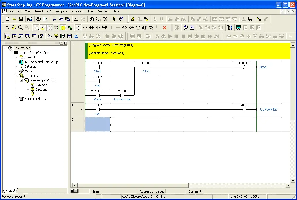
Refer to Chapter - 4 Working On-line.Changing a PLC in a ProjectTo change a PLC, double-click on the PLC object in the project workspace. In order to test theprogram, examine memory or monitor PLC operations, communications must first be established withthe PLC. An empty Ladder program is also displayed in the DiagramWorkspace.The initial project, program and PLC settings are made whilst the PLC is offline.
CX PROGRAMMER LADDER PLUS
Refer to the CX-Server User Manual for furtherinformation.The project workspace is updated with a new PLC entry plus its associated global symbol table, IO Table,PLC Settings, Memory data and Program. The Change PLC dialogue isdisplayed, part of the CX-Server application.3.Setup the PLC as required. Additional PLCs and programs can be added.Revision 2.0CHAPTER 4 – ReferenceOMRONUse the following procedure to add a PLC to a project.1, 2, 3…1.Select the Project object in the project workspace.2.Select the New PLC button from the toolbar. When a project is initiallyconfigured, it contains one PLC and one program.
CX PROGRAMMER LADDER SERIAL
Serial and network communications can be made using communication types althoughthese are dependent upon the type of communicating PLC.Adding a PLC to the ProjectCX-Programmer supports multiple PLC and multiple program support. Two methods of communication are available: serial communications and networkcommunications. For example, the CV-seriesand CS1-series require setting up the IO Table via the IO Table object in the project workspace and usingthe PLC settings object to establish specific PLC characteristics.Connection to the PLC requires the specification of the type of communications interface to be used toconnect to the PLC.
CX PROGRAMMER LADDER FULL
These PLCsdo not really have to be connected unless communications with them are to occur.Ī full description ofthe communications possibilities for C-series PLCs, CV-series PLCs and CS1-series PLCs is providedin the CX-Server User Manual.The PLCs selected also affect which setup procedures need to be performed. Refer to Chapter 9 - Memory Card Component of the CX-Server User Manual.PLCs and ProjectsA project file contains one or more PLCs that are (potentially) connected to the computer. Refer to the CX-Server User Manual.♦Memory Card. Refer to Chapter 8 - PLC Error Component of the CX-Server User Manual ♦Clock. Refer to Chapter 7 - Data Trace/Time Chart Monitor Componentof the CX-Server User Manual ♦Error Log. Refer to Chapter 6 - PLC Setup Component of the CX-Server User Manual ♦Data Trace/Time Chart Monitor. Refer to Chapter 5 - IO Table Component of the CX-Server User Manual ♦PLC Settings. Refer to Chapter 4 - PLC Memory Component of the CX-Server User Manual ♦IO Table. It can then be repositionedif necessary by dragging and dropping.4.To move a button from an existing toolbar to the new one, select the button to bemoved and drag and drop it in position in the new toolbar.5.If a particular button is not visible click the Commands tab and from the list ofCategories select the type of buttons to be viewed6.Click on the selected button and drag and drop it in position in the new toolbar.7.To delete a customised toolbar select it from the list of toolbars and click the Deletebutton.Revision 2.0OMRONCHAPTER 4 – ReferenceCHAPTER 4ReferenceThis chapter introduces the objects contained in the project workspace and discusses their associatedcommands and features.The following components, which are available either from the project hierarchy or from main menu,form part of the CX-Server software.♦PLC Memory. The new toolbar will then beadded to the list of toolbars and displayed on the screen.

This displays the New Toolbar dialogue.CHAPTER 3 – Project ReferenceOMRON3.Enter a name for the new toolbar and click OK.

The Toolbars dialogue is displayed.2.Click the New button.

Notehowever that although all the buttons can be removed from a default toolbar the toolbar it’s self can notbe deleted.Use the following procedure to create or delete a customised toolbar.1, 2, 3…Revision 2.01.Select Toolbar from the View menu. Toolbars created in this way can also be deleted.


 0 kommentar(er)
